| Home | Accessory Kit | Marsh CD Collection | Library | Contact Us |
Chapter #7
1934 Rife Ray #3
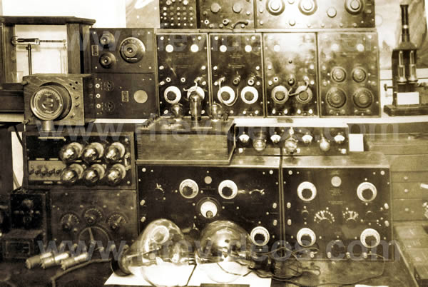
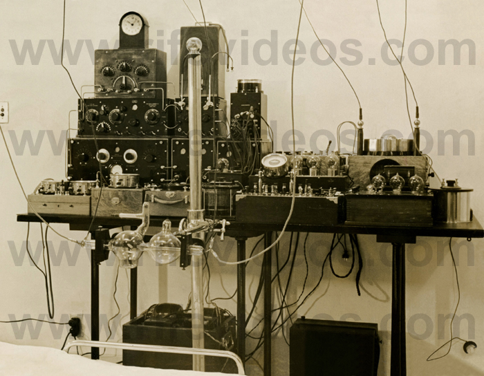
Rife Machine used in the 1934 clinic
 |
1) This was a regenerative instrument that used a ray tube.
2) It consisted of two Kennedy Regenerative Receivers (the model numbers were the 110 and 281). These two receivers made it possible to have a combination of one low-frequency oscillator and one high-frequency oscillator or two high-frequency oscillators.
3) The frequency output was a sine wave gated into a damped wave.
4) Power usage was from batteries. Output to the ray tube was listed as 50-watts output RF.
This instrument was described in a document believed to have been written by Jack Free, one of Dr. Rife's lab assistants. We will quote the portion of that document that pertains to this instrument:
"In 1923 more appropriate apparatus [Rife Ray #2 when improved became the Rife Ray #3] was assembled and used. The different frequencies were generated by a tube oscillator with many stages of amplification, the final stage being a 50-watt Telefunken tube.
This amplified frequency was in turn fed into an output tube, and as the voltage at this point was quite small, it was found necessary to apply external voltage across the anode and the cathode of the output tube [ray tube] to act as a carrier wave for the frequencies that were generated in the apparatus.
The output tube was constructed with a double expansion bulb, blown from quartz, using platinum anode and cathode it having a 45° target for directional effect. No heat is generated in output tube-temperature constant. The frequency control of the instrument was exact to a fraction of a wavelength making it possible to coordinate the frequency in each pathogenic micro-organism with its own wavelength of frequency delivered from the instrument.
The current supply for the whole apparatus was supplied by batteries and generators.
During the next eight years these experiments continued and with the aid of the Rife super-microscope and the frequency instruments the coordinating frequencies (termed mortal oscillatory rate MOR) of most of the pathogenic micro-organisms were found and recorded including the frequencies of many of the virus or filter passing forms of these organisms." (Development of the Rife Ray and use in devitalizing of pathogenic micro-organisms).
Dr. Rife was asked by Dr. Milbank Johnson M.D. to write a description of his Rife Ray #3 instrument in 1935. Dr. Rife had Jack Free, his lab assistant; include this description in a letter that Jack Free wrote to Dr. Milbank Johnson. Below is Dr. Rife's description.
RIFE: "The basic principle of this device is the control of a desired frequency. These frequencies varying upon the organisms being treated.
The frequency is set which controls the initial oscillator, which in turn is run through six stages of amplification, the last stage driving a 50-watt output tube.
The frequency with its carrier wave is transmitted into an output tube similar to the standard X-ray tube but filled with a different inert gas. This tube acts as a directional antenna.
The importance in the variable control of these frequencies is that each pathogenic organism being treated is of a different chemical consistency, the consequence being they carry a different molecular vibratory rate. Each one in turn under these conditions requires a different frequency or vibratory rate to destroy." (Letter from Jack Free to Dr. Milbank Johnson M.D., December 17, 1935)
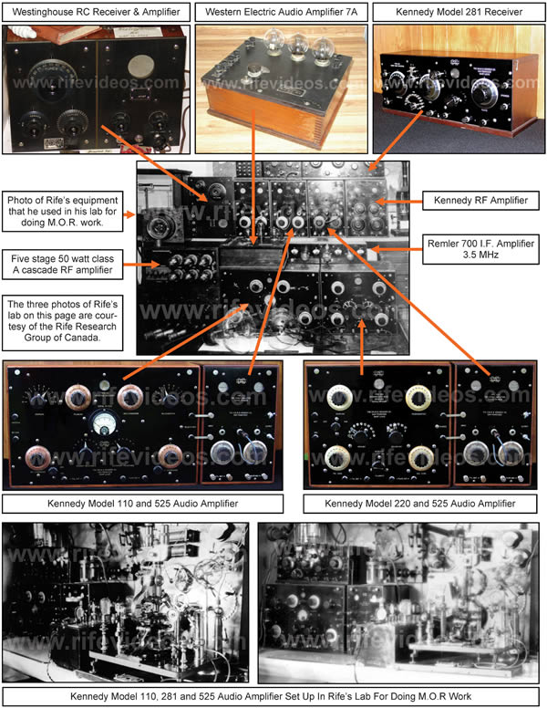
This Rife Machine was used in the 1934 clinic by Dr. Milbank Johnson M.D. If you look at the bottom of the above photo of the Rife Ray #3 you can see part of the bed railing and mattress where they treated the patients. If you look at the table you can see that the instrument was not a one-piece instrument but had many components. This Rife Machine has always been considered the best instrument used by Dr. Rife because it produced the results of the 1934 cancer and tuberculosis clinic. Those interested in the work of Dr. Rife have always wanted to know how this instrument worked. They have also wondered what equipment he used. This has been one of the biggest Rife mysteries. There have been all kinds of speculation on how his first instrument worked. What was its waveform? What was the frequency range? Could it generate audio frequencies? Was it super-regenerative (as he wrote on his lab notes), or was it just regenerative? All of these things have remained mysteries for over fifty years. It was generally believed that the 1934 instrument was custom made for Dr. Rife. However, if the equipment had not been custom made, the mystery could be solved. And today, thanks to some great detective work done by Mr. Peters, the mystery, in fact, is now solved. The instruments were not custom made. They were standard off-the-shelf frequency generating equipment that Dr. Rife purchased. The equipment and frequency ranges are now known.
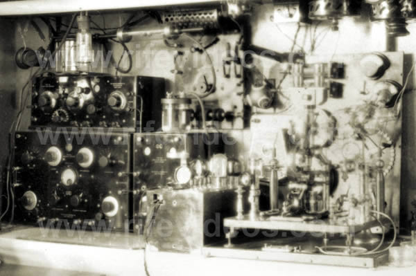
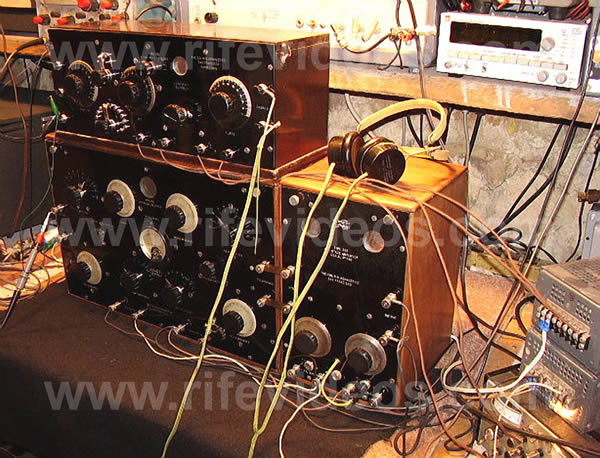
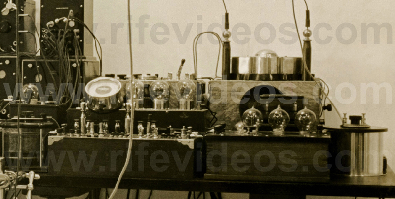
Below is another photo that shows more of Dr. Rife's equipment. It was when Mr. Peters was looking at this photo that he recognized the Kennedy frequency generating equipment.
Dr. Rife most likely stacked it all up on a table and took a picture of it after he started to use the newer equipment built for him in 1935. This photo, amongst others, made it possible to figure out the equipment Dr. Rife used. This photo has been provided courtesy of Jason Ringas of Rife Research Group of Canada. Here in this paper, you will be able to see the actual equipment along with the selling advertisements of the 1920s that give the specifications of the equipment.
We will now look at each piece of equipment and take an in-depth look at the specifications of each. All pieces of equipment except the ray tubes and possibly the five-stage amplifier were considered off-the-shelf equipment. This means that this was standard frequency generation equipment which could be purchased from companies in the 1920s. Although they are regenerative receivers, they could output whatever frequency Dr. Rife wanted to use when the regenerative circuit was turned up. Dr. Rife used top-of-the-line Kennedy equipment from the Colin B. Kennedy Company, which built some of the most accurate, high-quality equipment that could be purchased in 1923. It was also some of the most expensive equipment to purchase. We will now take a look at the next photo, shown below.
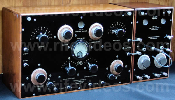
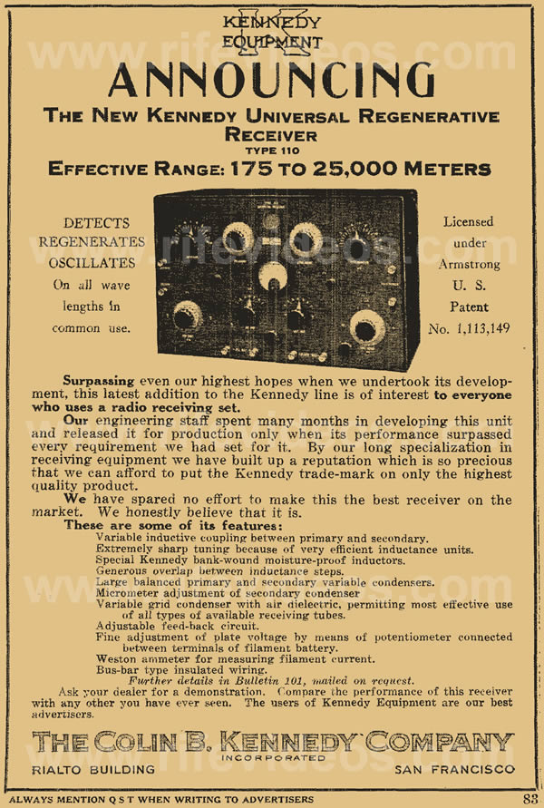
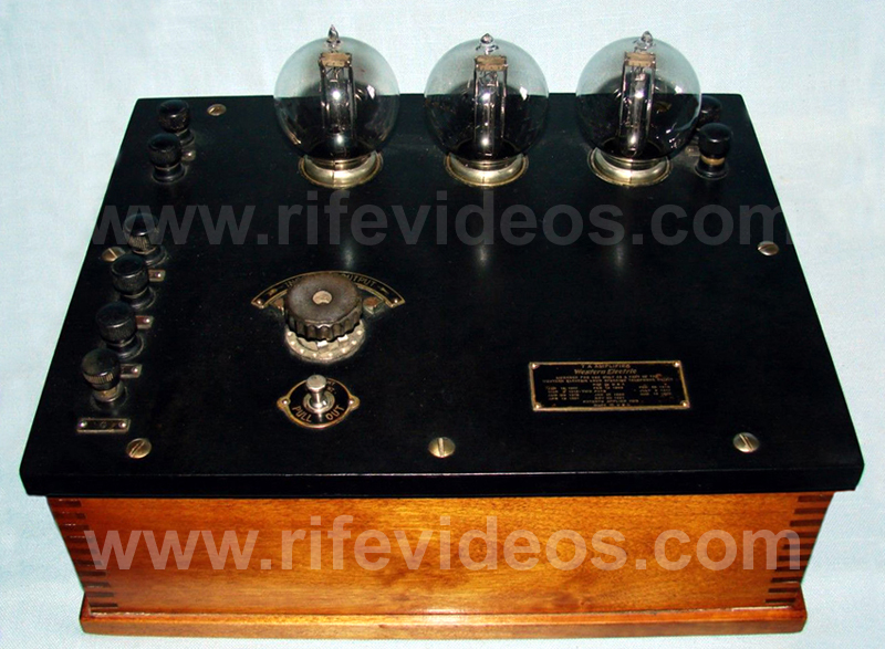
This photo is one of several photos of Dr. Rife’s lab instruments. The bottom two pieces of equipment were the Kennedy Receiver Model 110 connected to the Kennedy Two-Stage Audio Amplifier Model 525. The other piece of equipment sitting on top of the Kennedy Receiver Model 110 we will look at later. Below are two more photos. The first photo is a better photo of this old antique equipment. The second photo is the 1923 advertisement from the Colin B. Kennedy Company which provides the frequency range and features of this regenerative receiver. It also gives the effective frequency range from 175 to 25,000 meters or from 12,000 Hertz to 1,700,000 Hertz.
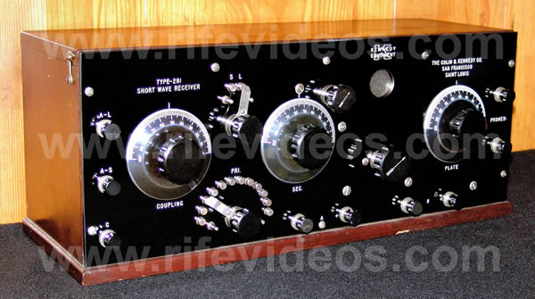
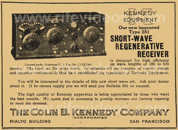
The Kennedy Model 110 could actually go to about 1,800,000 Hertz. The Kennedy Company was just being conservative in its advertisement. The next instrument that was on top of the Receiver Model 110 in Dr. Rife's lab photo is the Kennedy Short-Wave Regenerative Receiver Model 281. Below is a photo of the Kennedy Receiver Model 281. Below the 281 is a picture of the 1923 Kennedy 281 advertisement.
This Kennedy 281 instrument had an effective range from 185 meters to 620 meters or from 483,000 Hertz to 1,620,000 Hertz. This instrument could actually go to about 1,800,000 Hertz. Kennedy Company again being conservative.
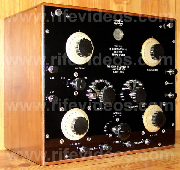
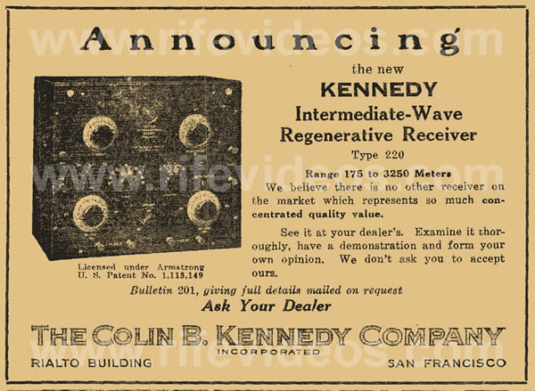
Above, in the original lab photo, which showed all of Dr. Rife's equipment stacked up on a table, we see another Kennedy Regenerative Receiver, this being the Kennedy Model 220. The next photo, shown below, is a photo of this instrument. Its effective frequency range was from 175 meters to 3250 meters or from 92,000 Hertz to 1,700,000 Hertz. It could also go to about 1,800,000 Hertz. All three models of this Kennedy equipment could go higher in frequency than the advertisements state. Below the Kennedy Model 220 photo, we see the 1923 advertisement for the Kennedy 220 instrument.
Now that we have all the frequency generating equipment identified we can now come to some conclusions. All of this Kennedy equipment was a sine wave. The square wave was not used or even generated in this old equipment. The Kennedy Receiver Model 110 had a frequency range from 12,000 to about 1,800,000 Hertz. This shows that Dr. Rife’s instruments had the ability to output audio frequencies, a fact that he mentioned in his 1961 deposition. The only audio frequencies he could have used would have been modulated from this equipment. Dr. Rife also mentioned in his 1961 deposition that he balanced the audio on a carrier which would have been a modulated waveform.
What is really important to understand is the fact that none of the Kennedy equipment that Dr. Rife used could output a direct frequency higher than about 1.8 Megahertz (MHz). This fact changes a lot of things with regard to his lab notes dated before 1934. There are two frequencies listed on each lab note as the frequencies used to devitalize that organism. For the BX cancer virus, the lab note gives 11,780,000 Hertz and 17 6/10 meters or 17,033,000 Hertz. Since it was impossible for Dr. Rife to directly output these two frequencies using the Kennedy equipment then these two frequencies must be harmonics of some lower frequencies. In Dr. Rife’s lab photos of the Rife Ray #3, there are two Kennedy receivers connected together. Because they were connected together this makes it possible to output two frequencies simultaneously. Dr. Rife’s lab notes also say “wavelength of super regeneration of audion tube” (WSR). In super-regeneration, two frequencies are always used. These facts also show that Dr. Rife was mixing two frequencies to produce the frequency that would devitalize an organism.
Back in the 1920s and 1930s, it was difficult to measure an exact frequency. Dr. Rife also found it difficult to return to a specific frequency relying only on the accuracy of the Kennedy dials. Today with our modern technology it is easy to do this. Dr. Rife needed to be able to return to the same frequency every time regardless of the limits of his equipment. So he used a method that would make this accuracy possible.
In order to do this, he used the WSR or “wavelength of super regeneration” to help him re-find the frequency for each organism when he used his Kennedy equipment. The problem is the two specific frequencies listed on each lab note do not match the MOR’s or the frequencies that would devitalize the organism as was recorded later. In previous writings of this report, it was believed that Dr. Rife had misread his frequencies. Most believed this is what happened, but, some new information has come to light due to the efforts of Mike Fayer. This new information shows that Dr. Rife did not misread his frequencies as claimed by his engineer Philip Hoyland. The following statements taken from the 1939 Beam Ray Trial is the main reason why it was believed that Dr. Rife misread his frequencies. We quote:
COMPARET: “Now going back to your assumption that Dr. Rife knew the frequencies, had Mr. Hoyland ever told you that Dr. Rife knew them?”
EDWARDS: “No, he told me that Dr. Rife only thought he had them.”
COMPARET: “What did you think that meant?”
EDWARDS: “Well, Mr. Hoyland told me about that time [1934 and before], that Dr. Rife measured the frequencies only by the length of the wire and that he did not take other factors into consideration.” (Beam Ray Trial Transcript #1553-1555).This quote along with the fact that Dr. Rife’s lab note frequencies did not match later readings of his frequencies is what led to the belief that Dr. Rife misread his frequencies. The new information indicates that he read harmonics of his frequencies and within these harmonics was the actual frequency, or harmonic, that would devitalize the microorganism. Also, the harmonic which devitalized the microorganism would mathematically match up with the specific frequency read at a later date by Dr. Rife and Philip Hoyland. What should also be pointed out is that it is apparent that Dr. Rife did not know the actual frequency of each organism. Knowing the actual frequency and knowing a harmonic is two different things. Because Dr. Rife did not know the specific numerical frequency for each organism is probably the reason why Dr. Rife’s engineer, Philip Hoyland, told Edwards that Dr. Rife didn’t measure his frequencies correctly. We should point out that not knowing the frequencies or misreading the frequencies is different than reading a harmonic. Now let us discuss a little history.
With Dr. Rife’s approval, Philip Hoyland was hired by Dr. Milbank Johnson, M.D., and the University of Southern California Special Medical Research Committee in 1935 to build a more up-to-date portable frequency instrument to be used for their research. Dr. Rife’s 1934 instrument was cumbersome because it was not just one, but several, pieces of equipment that were difficult to move and use. In order to build the new instrument, Philip Hoyland needed to know what frequencies Dr. Rife was using. Dr. Rife could have just given Philip Hoyland a copy of the frequency ranges that the lab notes covered and he could have built the instrument from that information. But this is not what happened. Philip Hoyland brought his “standard oscillator” into Dr. Rife’s laboratory to read his frequencies. Dr. Rife and Philip Hoyland went through the long process of putting the many organisms under the microscope and determining what the specific frequency was for each organism when it was devitalized. Had Dr. Rife known the actual numerical frequencies then this testing wouldn’t have been necessary. We also do not know how long this process took and it could have taken months to complete this work. Philip Hoyland could have mathematically calculated all of the harmonic frequencies and sideband frequencies produced from the mixing of two frequencies, one from each Kennedy receiver.
What is apparent from this testing is the fact that Dr. Rife wanted to know exactly what his frequencies were. Philip Hoyland also needed to know what frequencies Dr. Rife was using in order to build the new instrument. While testifying on the stand in the 1939 Beam Ray trial, Philip Hoyland stated this about how he obtained the frequencies:
(1939 Beam Ray Trial Transcript #778).
HOYLAND: “They were taken off the last machine [the Kennedy equipment] that was built by Dr. Rife. I transferred them from one machine to another.”
At another point during the trial the transcript reads as follows: (Beam Ray Trial Transcript #905-916)
COMPARET: “In June of 1935 was when you made an agreement with the [transcript missing words] medical research to build a Rife Ray machine, [the Rife Ray #4] you did build it soon after that?”
HOYLAND: “Yes.”
COMPARET: “You had an agreement with them that all work was to be done under Dr. Rife’s direction?”
HOYLAND: “That’s what the contract called for.”
COMPARET: “Did you do this work without getting the frequencies from Dr. Rife?”
HOYLAND: “I recalibrated the machine according to the bacteria.”
COMPARET: “What specifically did you do that constituted this recalibration?”
HOYLAND: “I used a standard oscillator against his machine to see what frequencies he was using.”
COMPARET: “He set his machine and you measured his frequencies?”
HOYLAND: “Yes.”
COMPARET: “Did you make any memorandum of these particular frequencies?”
HOYLAND: “Yes, I gave Dr. Johnson and Dr. Rife a list of them.”
Later during the trial Dr. Rife was asked where the frequencies came from: (Beam Ray Trial Transcript #1290-1293)
JUDGE KELLY: “When you constructed this Beam Ray machine [from Kennedy equipment] you had a dial representing the frequencies or harmonics?”
RIFE: “We had many dials on the original machine [Kennedy Model 110].”
JUDGE KELLY: “Is that the machine Mr. Hoyland got the frequencies from?”
RIFE: “Yes, he took them off that old machine [Kennedy Model 110].”
From the court testimony given by Dr. Rife and Philip Hoyland, we see the frequencies were read by Philip Hoyland off of the Rife Ray #3 or Kennedy Model 110 and 281 and used in the next instrument which was the Rife Ray #4 (We will be discussing this instrument next).
Because the frequencies which Philip Hoyland read from Dr. Rife’s #3 instrument were different from the earlier lab note frequencies this has caused a lot of confusion. Anyone reading the above trial testimony can see that Philip Hoyland stated that the same frequencies he read from the Rife Ray #3 instrument were transferred from one machine to the next. Because the frequencies that Philip Hoyland read were all lower than 1,800,000 Hertz this shows that Dr. Rife was probably reading harmonics of the actual frequencies and recording these on his lab notes. This is the best explanation or reason why Dr. Rife had two frequencies written on his early lab notes (11,780,000 Hertz and 17,033,000 Hertz) for the BX cancer virus. Dr. Rife and Philip Hoyland’s reading of the frequencies indicate that Dr. Rife did not misread his frequencies; he just read harmonics of the frequencies. What is also interesting is the fact that all of the frequencies that were read in the laboratory testing could have been output by just one of Dr. Rife’s Kennedy receivers. The Kennedy Model 110 had this capability. Dr. Rife and Philip Hoyland, through this testing, establish the fact that only one frequency was needed to devitalize each organism instead of two. From this point on Dr. Rife regularly stated that each organism only required a single frequency to devitalize it. We will cover this information later.
SINER: “That was a long time ago, but, and remember, I was just copying what he [Dr. Rife] dictated.” (John Marsh Rife CD's - MP3 track 11)
This quote from Henry Siner shows that it was Dr. Rife who made the corrections to the lab note. The frequencies of 11,780,000 Hertz and 17,033,000 Hertz were both changed to 1,604,000 Hertz. With the new Rife Ray #4 machine, two frequencies mixed together were no longer needed or used. The single frequency for each organism, which was determined from the laboratory testing, was the only frequency used to devitalize each organism even though the Rife Ray #4 had the ability to mix two frequencies simultaneously.
Some wonder if Dr. Rife really understood that he may have been only reading harmonics. The following statement of Dr. Rife’s clearly shows he understood harmonics and how easy it was to read a harmonic frequency instead of the fundamental frequency. We quote:
RIFE: “I’ve talked to you [John Crane] and Verne [Verne Thompson] and other people too that there may be some of the frequencies that we are using that may be harmonics, you know...It’s not an impossibility that some of those frequencies may be a harmonic. We may not know the true frequencies of some of them. But it does the business. Maybe if we had the true frequency it would do it better because it has more power than a harmonic.” (John Marsh Rife CD's - CD 7 track 2)
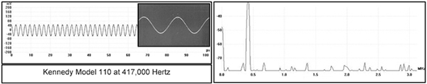
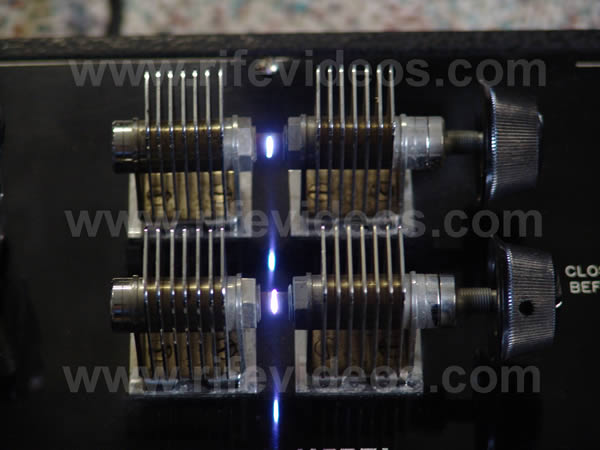
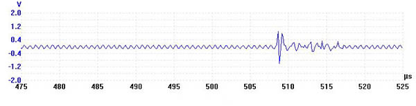
This quote clearly reveals that Dr. Rife understood harmonics and how they worked. Many have believed that Dr. Rife’s original Rife Ray #3 machine naturally had harmonics in its waveform. They have also wondered if output a sine wave waveform? Was the waveform distorted? The only way to answer these questions was to find a working Kennedy 110 and put it on a spectrum analyzer. Jason Ringas of the Rife Research Group of Canada and I contacted Henry Rogers the owner of the Western Historic Radio Museum (www.radioblvd.com) who owns two Kennedy 110's that are still operational. Henry Rogers knew nothing about Dr. Rife but agreed to let me come visit his location to check the readings of the Kennedy Model 110. He also owns a Kennedy 220 and a Kennedy Model 281, both of which are also in working condition. The Kennedy Company built top-of-the-line equipment and we were surprised to find out even after over 80 years, they still worked as well as they did when they were new. Very little attention is ever needed to get these instruments back in working condition because of the quality of their construction. So with the spectrum analyzer in hand, I went to see Henry Rogers and we put the Kennedy 110 on the spectrum analyzer to get the answers to our questions. Below is the reading of the waveform of the Kennedy Model 110 at 417,000 Hertz using a PicoScope 3205 spectrum analyzer. On the left is the waveform which proves that Dr. Rife was using a sine wave.
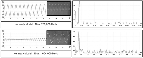
That question was finally answered. The spectrum analyzing of the frequency revealed that there were no harmonics in the waveform. The noise which shows up as little spikes comes from the power supply. These old receivers ran on batteries and when they are connected to batteries the noise in the circuit is greatly reduced. The amazing thing about the Kennedy Model 110 sine wave waveform was that it was picture perfect. This amazed us because everyone believed that the equipment that Dr. Rife used would have had a distorted waveform. No one that I have ever talked with believed that this old equipment was capable of producing a nearly-perfect waveform. It was as good as we can do today with our sophisticated modern frequency generating equipment. The fact that it produced no harmonics also amazed us. Below are the readings of the Kennedy Model 110 at 770,000 and 1,604,000 Hertz. At 1,604,000 Hertz the sine wave was still nearly perfect and it did not produce any harmonics. We checked all frequencies out to 50 Megahertz for harmonics and found none.
This testing showed that Dr. Rife’s Kennedy equipment output a sine wave waveform with no harmonics as long as it outputs a single frequency. But it is known that Dr. Rife had the Kennedy Model 110 and 281 connected together so that he could output two frequencies simultaneously. And this gives some explanation of how he produced the harmonics that were listed on his lab notes.
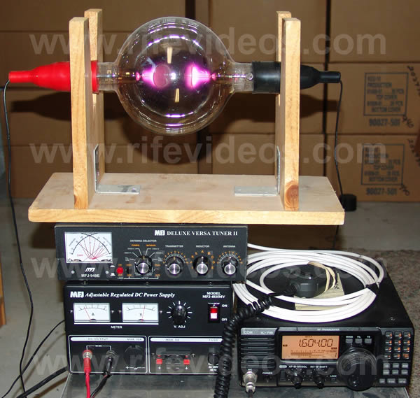
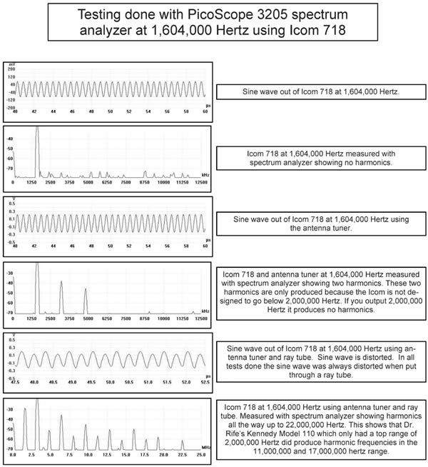
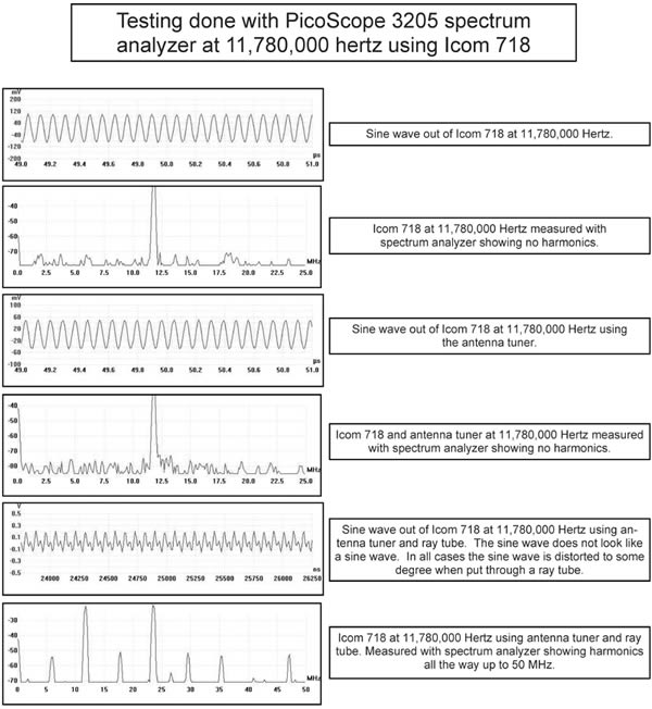
There is another factor that can also create harmonics. We knew that the noble gas he used in his ray tube could double the frequency that went through it. These types of tests have been done with plasma in laboratories in the past. So we decided to make some tests. Because we did not have the ability to connect the Kennedys up to a ray tube at Henry Rogers we decided to test an Icom 718 which we hooked up to a phanotron ray tube. This is the type of ray tube Dr. Rife used and is the only one we tested. We first tested to see what the sine wave looked like coming out of the Icom 718. We wanted to make sure that it did not produce any harmonics, and in fact, our testing showed it did not produce any harmonics. Then we hooked it up to the antenna tuner to see if the tuner distorted the waveform and produced any harmonics. We found it did not distort the waveform or produce harmonics through the antenna tuner except at 1,604,000 Hertz. This is only because the Icom is not supposed to output a frequency below 2,000,000 Hertz. Below this frequency, it will produce two harmonics (see graph on the next page). The other two frequencies we tested were 11,780,000 and 17,033,000 Hertz. These were the frequencies Dr. Rife recorded on his pre-1935 lab notes and neither of these produced harmonics through the antenna tuner. Then we put it through the ray tube. The ray tube didn’t just double the frequency - it also produced many harmonics that Dr. Rife could have read. This test showed that not only will mixing two frequencies together produce harmonics but the ray tube can also produce more harmonics. These tests prove that you can put a harmonic-free sine wave through a ray tube and get many more harmonics. The photo below is the Icom 718. The three graphs below the Icom 718 show the readings taken in this testing.
Below are the measurements that were taken with the PicoScope 3205 spectrum analyzer from the Icom 718 using the antenna tuner and ray tube at 11,780,000 Hertz. This was the first frequency Dr. Rife listed on his pre-1934 lab notes which was later changed to 1,604,000 Hertz.
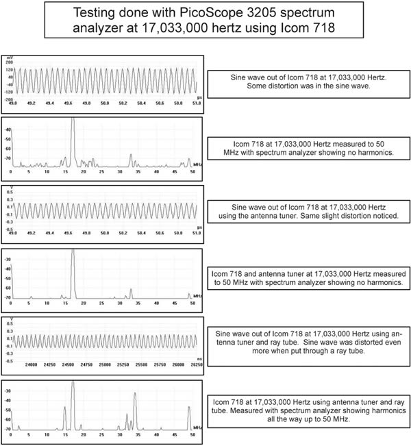
Below are the measurements that were taken with the PicoScope 3205 spectrum analyzer from the Icom 718 using the antenna tuner and ray tube at 17,033,000 Hertz. This was the second frequency on his pre-1934 lab notes which was recorded in meters. This was later changed to 187 meters which would give us a frequency of about 1,604,000 Hertz. This confirms that Dr. Rife was just reading a harmonic at 17,033,000.
The next group of photos shows Dr. Rife's equipment and photos of the individual pieces that make up his Rife Ray #3 instrument.
After having done this spectrum analysis testing and knowing that he could mix two frequencies producing harmonics, we now have a possible explanation of how Dr. Rife might have produced the higher harmonic frequencies found on his lab notes. The decision by Dr. Rife to have Philip Hoyland read the frequencies gave the single frequency that would devitalize each organism. We will again point out that from this time forward Dr. Rife always stated that each organism had its own specific individual frequency that would devitalize it. The reading of the BX cancer virus frequency was recorded as 1,604,000 Hertz instead of 11,780,000 and 17,033,000 Hertz. All of the rest of the frequencies for each organism also changed to frequencies within the capabilities of the Kennedy Model 110 to directly output.
When we read the Kennedy Model 110 the instrument was surprisingly accurate. Dr. Rife could have very easily hit the frequency he wanted within the tolerances he gave. He gave “ one-tenth of one meter” as a gage to show how close you had to be to an organism’s M.O.R. At 1,604,000 Hertz this would be 858 Hertz. He said if you were off by this amount the frequency wouldn’t work. With that in mind, it would be necessary to be within a few hundred Hertz of the BX M.O.R. in order to make sure the frequency was effective. The Kennedy instrument could hit within 200 to 300 Hertz very easily at 1,604,000 Hertz. After changing the dials and then coming back to the same settings, using the method he used, he could easily hit the correct frequency of any organism. It is interesting to note that Dr. Rife and Philip Hoyland read the frequencies they rounded off all but one frequency to the nearest thousandth. The testing of the Kennedy Model 110 shows that the frequency for the BX is most likely somewhere between 1,600,000 and 1,608,000 Hertz because the standard master oscillator that was used was accurate to about 1/4th of 1 percent. All of the frequencies are only close and this should be considered when using them. One fact that helps to point this out is Philip Hoyland read 1,604,000 Hertz for the frequency of the BX. He also gave 187 meters as the frequency. One hundred and eighty-seven meters is 1,603,168 Hertz. This is a difference of 832 Hertz and shows why the frequencies are only close. The frequency calculated by Mike Fayer from the pre-1935 lab note frequencies for the BX of 11,780,000 and 17,033,000 is 1,607,450. This frequency is also within the 1/4 of one percent accuracy of the 1930’s master oscillator used by Philip Hoyland to read the frequencies. The reading of these frequencies also showed that Dr. Rife did not misread his frequencies. He just read harmonics and within those harmonics was the frequency that would devitalize the organism.
So now that we know that Dr. Rife’s Kennedy Model 110, 220 and 281 only went to about 1,800,000 Hertz with harmonics going to about 20,000,000 Hertz (see next graph below). We have to ask this question: What frequency is really the true M.O.R? Is it the 1,604,000 Hertz or a harmonic of it? The actual M.O.R. frequency could have been very easily a harmonic, and Dr. Rife would have never known it. Since the possible mixing of the two frequencies and the ray tube is what may have produced these harmonics it may be very important to have all of these harmonics. Myth Busters, a cable television program did a test to see if they could break a crystal glass with sound waves. They found when they used only the fundamental frequency without the harmonics they could not break the glass. But when they used the harmonics along with the fundamental frequency then they were able to break the glass. This may or may not be pertinent but it is something that should be considered.
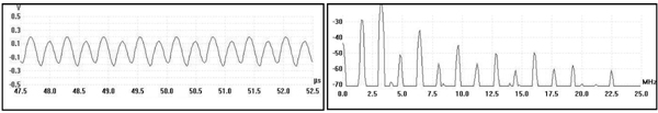
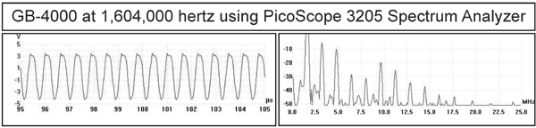
With this in mind, we decided to see if there was a way that we could duplicate the harmonics without having to use a ray tube. The next reading with the spectrum analyzer, top of the next page shows that if we distorted the sine wave no more than what the ray tube did we could produce the same harmonics as a ray tube.
The reading was done at 1,604,000 Hertz taken from an off-the-shelf GB-4000 Function Generator. This test showed it was very easy to duplicate the harmonics produced by a ray tube. We decided to test a triangle wave since the distorted sine wave out of the ray tube resembled it. It also produced the same harmonics as a ray tube. Then we gated an undistorted sine wave and it produced the harmonics. It is apparent that any sine wave frequency from any frequency generator when gated will produce harmonics.
We will now discuss Dr. Rife’s tuning of the Kennedy Receiver Model 110 using headphones. In the photo above you can see a set of headphones on the Model 525 audio amplifier. Headphones were used to tune the Kennedy Receiver Model 110 and Dr. Rife’s earlier instrument that he used before purchasing the Kennedy equipment.
When Dr. Rife set the MOR or frequency that would devitalize the organism he would tune it to that frequency using headphones. Bertrand Comparet, Rife’s attorney for the Beam Ray trial of 1939 made this statement when he was interviewed by Dr. John Hubbard:
COMPARET: “Way back in the old days, way, way back, Rife told me that the way he used to tune his instrument, which in those primitive days was, I guess, garbled. He would hook up headphones and turn the thing. He had a very keen musical sense of pitch and so on, and he would tune it in his headphones until he got the right pitch, and that was the frequency.” (1970’s Bertrand Comparet interview #89)
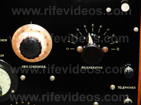
The headphones played an important role in tuning his Rife Ray #1 through the Rife Ray #3 machines. The Rife Ray #2 and #3 used the Kennedy Receivers. In the next photo, shown below, you can see the regeneration dial of the Kennedy Receiver Model 110. When you turned up the regeneration dial then the instrument would output frequencies. Instead of it being just a receiver it also made it an oscillator which would output frequencies. This dual capability is the reason Dr. Rife used them.
Jimi Harre explained how this may have worked if someone was using it to find a radio station. This same method was probably used by Dr. Rife to return to the MOR frequency for each organism because using the Kennedy numerical numbers, on the dials, was not very accurate. Back in the early days of radio, a person would tune to the radio station using the dial numbers. But when they got close to the radio station they would listen to tune it in perfectly because the dialed number may be a little different each time. This, in essence, is what Dr. Rife was doing. Here is his Mr. Harre’s quote:
HARRE: “Using any AM radio, tune in a station at the top end of the dial. Take one of the Kennedys and tune it to the same station. Adjust the regeneration on the Kennedy so it becomes an oscillator and tune it to "zero beat" with the AM radio station. Record the Kennedy dial settings as accurately as possible. Turn off the Kennedy and set its dials to zero. Wait a while and then turn it back on. Return to the same dial settings you previously recorded. Does the Kennedy still zero beat with the AM radio station? If it doesn't, the audio beat frequency will be the tuning error. Rife had difficulty returning to MORs when relying on the accuracy of the Kennedy dials. That is why he developed an alternative method using the WSR [wavelength of super-regeneration]."Real close" simply wasn't good enough for Rife.”
Using this method and listening with his headphones made it possible for Dr. Rife to accurately return to the MOR of each organism. This helped him to overcome the problems that the early 1920’s and 1930’s equipment had with accurately returning to the same frequency. Many people remember back in the 1960s and 1970’s how the car radio stations would seem to drift and they would regularly have to re-adjust the dial of their radio back onto the station they were listening too.
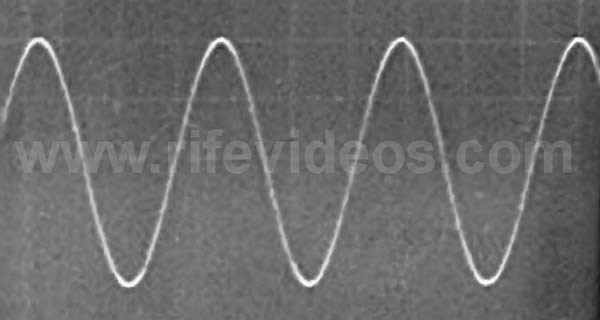
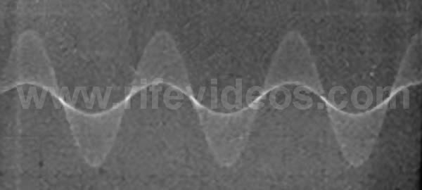
Now we will discuss how the Kennedy equipment could modulate audio frequencies from 12,000 Hertz and up. In the first photo, shown below, is how the waveform looks before modulation. The second photo, shown below, is how the waveform looks when an audio frequency is modulated onto a carrier frequency using the Kennedy equipment. Its modulated waveform looks different than today’s modulated waveforms but it still accomplished the goal.
We will now discuss Dr. Rife’s multi-stage-amplifiers that he used with the Kennedy equipment. These were most likely class A RC coupling cascade style amplifier. In the photos below we see three different styles of amplifiers. The first photo below is of his Rife Ray #3 at the 1934 Clinic. You can see 2 three-stage amplifiers. The one on the right is a Western Electric Amplifier 7A. The second photo below is a closeup of this same amplifier.
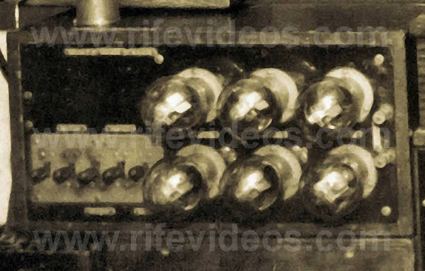
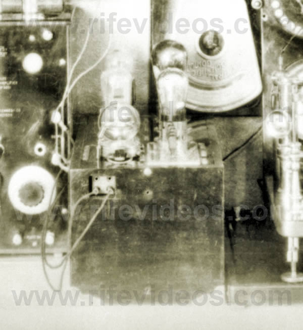
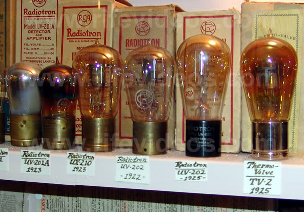
The Kennedy Receiver Model 110 only output about 1.5 to 3 volts. Dr. Rife needed to be able to amplify the signal to a high enough power level to make it effective. In the next three lab photos shown below, we see another one of Dr. Rife’s multi-stage-amplifiers. In the fourth photo, shown below, you can see the type of tubes he would have used in the early to mid-1920s.
These tubes would have made it so Dr. Rife could amplify the signal from the Kennedy Receiver Model 110 to about-50 watts in multi-stages. If you look at the above three photos of Dr. Rife’s multi-stage-amplifier you will see five switches. These five switches (representing five-stages) made it so he could choose different power levels determined by how many stages of amplification he wanted to use. With this configuration he could have easily produced the 50-watts he said he used. This 50-watts was the power level that was mentioned in the Rife CDs for this instrument.
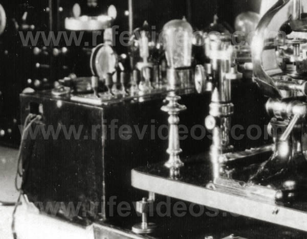
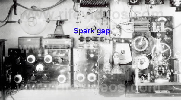
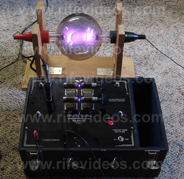
Ben Cullen, a close friend of Dr. Rife’s, mentions on the Rife CD's that Dr. Rife would light the ray tube with a separate power source. His lab photos show a spark gap transmitter which he probably used, in the 1920s, to light the ray tube. If you look at Dr. Rife’s lab photo, the first shown below, you can see the spark gaps. The spark gaps are right below the "Spark gap" writing put on the photo. The second photo, shown below, is an up-close photo of the spark gap transmitter diathermy from the 1920s. We purchased it so we could test the lighting of a ray tube with it. The third photo, shown below, is the lighting of the ray tube using this spark gap transmitter. It lit the ray tube with ease and could output more power than the ray tube could handle.
This spark gap transmitter would make it so Dr. Rife didn’t have any difficulties tuning the ray tube when he changed frequencies from a low frequency of 139,000 Hertz to a higher frequency of 1,604,000 Hertz.
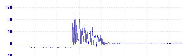
In the next photo, shown below, we see the waveform of this spark gap transmitter. The spark gap transmitter had a damped waveform and would have given him a damped wave carrier frequency most likely somewhere around one Megahertz. This transmitter we purchased has a frequency of 920 kHz. Dr. Rife would not have modulated frequencies onto this carrier wave but he would have just mixed the frequencies in the ray tube.
The next photo, shown below, is of a sine wave and spark gap damped waveform mixed together in the ray tube.
Mixing would have given him the combination of a damped wave and one or two sine wave frequencies, depending on if he used two sine wave frequencies simultaneously. We do not believe that Dr. Rife continued to use a spark gap transmitter because it would have made it impossible for him to read the ray tube harmonic frequencies that his ray tube output. This is because a spark gap outputs broadband noise that makes it impossible to read any harmonic frequencies. Dr. Rife must have only used the spark gap transmitter in his early 1920’s work. From the document "Development of the Rife Ray", we learn what he replaced the spark gap transmitter with. Quote:
"And as the voltage at this point was quite small, it was found necessary to apply external voltage across the anode and the cathode of the output tube (ray tube) to act as a carrier wave for the frequencies that were generated in the apparatus." (Development of the Rife Ray and use in devitalizing of pathogenic micro-organisms)
It appears that the spark gap transmitter accomplished two important things. One: It lit the ray tub with an external voltage. Two: It produced a high potential voltage spike in the frequencies. Later Dr. Rife used a DC voltage transformer much like a neon light transformer to light his ray tube. Then he added an audio pulsing circuit to create a high potential voltage spike.To better understand the reason why a high potential voltage spike or rise is important we need to jump forward in the history of Dr. Rife's instruments to 1936-1937. The Beam Ray Laboratory instrument built by Philip Hoyland was built at this time and it had a fixed audio frequency pulsing circuit. The audio frequency that it produced was modulated with the RF frequencies it output. This audio pulsing circuit would have given Dr. Rife’s frequencies a very high potential voltage spike almost identical to the damped wave of the spark gap. John Crane made this statement when he was narrating Dr. Rife’s lab film. We quote:
CRANE: “Now the spikes that you see on the frequencies are the lethal part that kill and devitalize the virus. They are the resonant peaks of the frequencies which increase the voltage to a very high potential which the cells of the virus wall cannot tolerate and they break up into many pieces and are destroyed.” (Watch Dr. Rife’s 1939 Lab Film Narrated by John Crane in the 1970s).
The modulated audio frequency in the 1936-1937 Beam Ray Laboratory instrument was in the shape of a damped wave. With both the Rife Ray #4 and the Beam Ray Laboratory instruments having waveforms in the shape of a damped wave doesn't seem like a coincidence. When Dr. Rife discontinued using the spark gap and replaced it with an external high voltage current to act as a carrier frequency he would have had to develop a new method of creating this high potential voltage rise in his frequencies. It appears, with the help of Lee Deforest, that Dr. Rife must have developed this audio frequency pulsing (gating) circuit for his instruments. It is apparent that this pulsing or gating of the M.O.R frequencies may be the reason why Dr. Rife was able to devitalize the many microorganisms he tested. Though many today have also used Dr. Rife’s frequencies without this pulsing or gating with good results.
Dr. Rife described the method he used to find these frequencies on the Rife audio CDs.
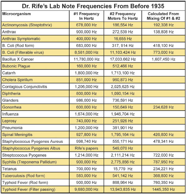
RIFE: “Because when I check on that thing and look through that microscope hour after hour day after day, tuning that damn thing [Kennedy 110] to find something that will kill that bug. And every hour or half an hour, whatever is required, I put a new fresh culture under the microscope and keep that on and I find something that folds it up, alright!” (John Marsh Rife CDs - CD 7 track 2)It was a very tedious task to find a frequency that would devitalize and organism. Dr. Rife recorded all his frequencies on lab notes. Even though his lab notes do not appear to have the correct frequencies on them many people want to know those frequencies anyway. Below is a chart of these harmonic lab note frequencies which he recorded prior to 1935. If you want a higher resolution copy of this chart click here. Each lab note had two frequencies. One was listed in cycles per second and the second was listed in meters. For the purpose of making this report easier to understand the meter wavelengths on Dr. Rife’s lab notes have been converted to cycles per second or Hertz. You will notice that there are two audio frequencies listed for organisms that are above 12,000 Hertz. They are the only audio frequencies ever listed by Dr. Rife for any organism. One of them was changed to a higher RF frequency when Philip Hoyland read the correct frequencies in 1935 when he built the Rife Ray #4. Most likely the other audio frequency was really a higher RF frequency. Also included in the chart are the frequencies calculated by Mike Fayer from the mixing of the two frequencies listed on the pre-1935 lab notes. These show that Dr. Rife did not misread his frequencies.
Chapter Summary: The Rife Ray #3 frequency generating equipment which Dr. Rife purchased back in 1923 was made by the Collin B. Kennedy Company. It mainly consisted of the Kennedy model 110 and model 281 to produce its frequencies. This equipment was regenerative but when two frequencies were mixed it became super-regenerative. Its frequency range, when the model 110 and model 281 were connected together, was from about 12,000 Hertz to about 1,800,000 Hertz. Its power output through the ray tube was about 50 watts. All of the frequencies it output were mostly in the AM radio band of frequencies. This equipments frequency range now explains why all of Dr. Rife's frequencies were less than 1.8 million Hertz as listed on the Rife Ray #4 documents. The Rife Ray #3 was the instrument that was used by Dr. Rife and Dr. Milbank Johnson M.D., back in the 1934 clinic on cancer and tuberculosis patients.
In chapter 8, we will look at Dr. Rife's Rife Ray #4 machine and the frequencies which Dr. Rife and Philip Hoyland read from the Rife Ray #3 machine and used in the Rife Ray #4 machine. We will compare them with the frequencies in the chart above which were calculated from the mixing of frequency #1 and frequency #2 found on his pre-1934 lab notes.